Showing posts with label a. Show all posts
Showing posts with label a. Show all posts
Friday, December 27, 2013
Build a 10 Amp 13 8 Volt Power Supply Circuit Diagram
Sometimes amateurs like to home-brew their power supplies instead of purchasing one off the shelf at any of the major ham radio retail dealers. The advantage to rolling your own power supply is that it teaches us how they work and makes it easier to troubleshoot and repair other power supply units in the shack. It should be noted that there is no real cost advantage to building your own power supply unless you can get a large power transformer and heat sink for a super low price.
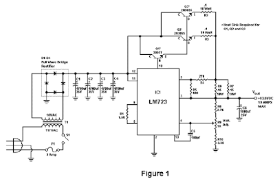
Of course rolling our own gives us the ability to customize the circuit and make it even more reliable than commercial units. The circuit in Figure 1 will give us 10 amps (12 amps surge) with performance that equals or exceeds any commercial unit. The circuit even has a current limiting feature which is a more reliable system than most commercial units have. Just like other commercial units, this circuit uses the LM723 IC which gives us excellent voltage regulation. The circuit uses 3 pass transistors which must be heat sinked. Resistor R9 allows the fine tuning of the voltage to exactly 13.8 volts and the resistor network formed by resistors R4 through R7 controls the current limiting.
The LM723 limits the current when the voltage drop across R5 approaches .7 volts. To reduce costs, most commercial units rely on the HFE of the pass transistors to determine the current limiting. The fault in that system is that the HFE of the pass transistors actually increases when the transistors heat up and risks a thermal runaway condition causing a possible failure of the pass transistors. Because this circuit samples the collector current of the pass transistors, thermal runaway is not a problem in this circuit making it a much more reliable power supply.
The only adjustment required is setting R9 to the desired output voltage of anywhere between 10 and 14 volts. You may use a front panel mounted 1K potentiometer for this purpose if desired. Resistor R1 only enhances temperature stability and can be eliminated if desired by connecting pins 5 and 6 of IC-1 together. Although it really isn’t needed due to the type of current limiting circuit used, over voltage protection can be added to the circuit by connecting the circuit of Figure 2 to Vout. The only way over voltage could occur is if transistors Q2 or Q3 were to fail with a collector to emitter short. Although collector to emitter shorts do happen, it is more much more likely that the transistors will open up when they fail.
10 Amp 13.8 Volt Power Supply Circuit Diagram
I actually tested this and purposely destroyed several 2N3055’s by shorting the emitters to ground. In all cases the transistors opened up and no collector to emitter short occurred in any transistor. In any event, the optional circuit in Figure 2 will give you that extra peace of mind when a very expensive radio is used with the power supply. The circuit in Figure 2 senses when the voltage exceeds 15 volts and causes the zener diode to conduct. When the zener diode conducts, the gate of the SCR is turned on and causes the SCR to short which blows the 15 amp fuse and shuts off the output voltage.
A 2N6399 (Tech America) was used for the SCR in the prototype but any suitable SCR can be used. While over voltage protection is a good idea, it should not be considered a substitute for large heat sinks. I personally feel the best protection from over voltage is the use of large heat sinks and a reliable current limiting circuit. Be sure to use large heat sinks along with heat sink grease for the 2N3055 transistors. I have used this power supply in my shack for several months on all kinds of transceivers from HF, VHF to UHF with excellent results and absolutely no hum. This power supply will be a welcome addition to your shack and will greatly enhance your knowledge of power supplies.

Parts
R1 1.5K ¼ Watt Resistor (optional, tie pins 6 & 5 of IC1 together if not used.)
R2,R3 0.1 Ohm 10 Watt Resistor (Tech America 900-1002)
R4 270 Ohm ¼ Watt Resistor
R5 680 Ohm ¼ Watt Resistor
R6,R7 0.15 Ohm 10 Watt Resistor (Tech America 900-1006)
R8 2.7K ¼ Watt Resistor
R9 1K Trimmer Potentiometer (RS271-280)
R10 3.3K ¼ Watt Resistor
C1,C2,C3,C4 4700 Microfarad Electrolytic Capacitor 35 Volt (observe polarity)
C5 100 Picofarad Ceramic Disk Capacitor
C6 1000 Microfarad Electrolytic Capacitor 25 Volt (observe polarity)
IC1 LM723 (RS276-1740) Voltage Regulator IC. Socket is recommended.
Q1 TIP3055T (RS276-2020) NPN Transistor (TO-220 Heat Sink Required)
Q2,Q3 2N3055 (RS276-2041) NPN Transistor (Large TO-3 Heat Sink Required)
S1 Any SPST Toggle Switch
F1 3 Amp Fast Blow Fuse
D1-D4 Full Wave Bridge Rectifier (RS276-1185)
T1 18 Volt, 10 Amp Transformer Hammond #165S18 (Tech America 900-5825)
R1 1.5K ¼ Watt Resistor (optional, tie pins 6 & 5 of IC1 together if not used.)
R2,R3 0.1 Ohm 10 Watt Resistor (Tech America 900-1002)
R4 270 Ohm ¼ Watt Resistor
R5 680 Ohm ¼ Watt Resistor
R6,R7 0.15 Ohm 10 Watt Resistor (Tech America 900-1006)
R8 2.7K ¼ Watt Resistor
R9 1K Trimmer Potentiometer (RS271-280)
R10 3.3K ¼ Watt Resistor
C1,C2,C3,C4 4700 Microfarad Electrolytic Capacitor 35 Volt (observe polarity)
C5 100 Picofarad Ceramic Disk Capacitor
C6 1000 Microfarad Electrolytic Capacitor 25 Volt (observe polarity)
IC1 LM723 (RS276-1740) Voltage Regulator IC. Socket is recommended.
Q1 TIP3055T (RS276-2020) NPN Transistor (TO-220 Heat Sink Required)
Q2,Q3 2N3055 (RS276-2041) NPN Transistor (Large TO-3 Heat Sink Required)
S1 Any SPST Toggle Switch
F1 3 Amp Fast Blow Fuse
D1-D4 Full Wave Bridge Rectifier (RS276-1185)
T1 18 Volt, 10 Amp Transformer Hammond #165S18 (Tech America 900-5825)

Tuesday, April 9, 2013
Up Down Timer Circuit For A Power Antenna
This up/down timer circuit was designed to control a power antenna on a late-model vehicle. Normally, this vehicle uses a body computer to control the antenna. However, the person who owned the vehicle wanted to install his own high powered audio stereo system. The original stereo system was tied in with the body computer and this meant that a separate antenna controller was required for the after-market sound system. Also, the power antenna fitted did not have limit switches inside, hence the need for a timed control circuit. Heres how the circuit works. first, assume that the radio antenna control output is not switched on - ie, the radio is switched off.
In that case, relay RLYC will be off and so relay RLYA will also be off, as is the motor. Conversely, when the radio is switched on, the radio antenna control output line switches to +12V. And when that happens, RLYC closes its contacts and applies power to the circuit. As a result, C2 (330OF) quickly charges via D4, while Q4 is biased on via D5 and R5. This ensures that Q3 and relay RLYB remain off. At the same time, Q2 is is turned on, thus turning on RLYA and applying power to the motor. This drives the antenna in the up direction. During this time, C1 charges via R2.
Circuit diagram:
Up/Down Timer Circuit Diagram
When the voltage across the capacitor reaches +8.1V, Q1 turns on via ZD1 and so Q2 turns off and switches off the relay - ie, this gives the "up" timeout. Using the values shown for C1, R2 and ZD1 gives an "up" duration of approximately 6 seconds - long enough to fully extend the antenna. D1 discharges C1 (via resistor R1) when the +12V supply is later removed.
When the radio is switched off (or a CD placed into the stereo unit), the radio antenna control output switches back to 0V. This does several things: first, it turns Q4 off and this allows Q3 to turn on due to the stored charge in C2. Q3 and RLYB now turn on for about six seconds - ie, while C2 discharges via R4 - and this switches power to the motor in the opposite direction to drive the antenna down. Diodes D4 and D5 are there to prevent C2 from discharging back via the circuitry around on Q1 and Q2.
Author: Peter Howarth - Copyright: Silicon Chip ElectronicsFriday, April 5, 2013
A Pioneer In Their Own Right The Pioneer Car Stereo
Look at any good car stereo system and you’ll probably see a Pioneer car stereo unit plugged into the console. Alongside with quality speakers and a strong lineup of accessories like LCD panels and navigational devices, Pioneer products/Pioneer car stereos have earned a huge following the world over.
The Pioneer Company is a Tokyo-based corporation, and is one of the world leaders in digital entertainment products. The Pioneer Company was first founded in 1938 in Tokyo as a small radio and speaker repair shop business but today, they are recognized as a leader in technology advancements in the consumer electronics industry.

The company is truly deserving of their name. They are respected for many innovations such as interactive cable TV, the Laser Disc player, developing the first Compact Disc player for the car and the first detachable face car stereo, DVD and DVD recording, plasma display, and organic electroluminescent display. Their strength in optical disc and display technology is complemented by its state-of-the-art software products and manufacturing capabilities.
Nowadays, Pioneer car stereo units are not just simple head units. A car stereo can easily be comprised of several items built into the console of the car. Hardware like navigational devices, DVD players with LCD panels, coupled with the standard array of compact disc, mp3 and cassette players now usually go together. One would be hard-pressed not to acquire all of these, as it is such a delight to see these units work harmoniously. But traditionally, a Pioneer car stereo unit is a head unit with a radio, cassette and cd player. No matter how bare-bones this might sound, anyone will surely be impressed with the sound quality and features a Pioneer car stereo can boot.
Something like the DEH-P90HDD Pioneer car stereo single CD player head unit. The DEH-P90HDD allows you to record CD Audio (from the unit itself or from a changer) onto a 10GB hard disc drive, which holds about 200 audio CDs (using ATRAC3 digital compression). Your CDs are recognized by the pre-installed Gracenote CDDB database, which includes auto-playlists that make finding a specific CD easy. This Pioneer car stereo unit can also play your MP3 CDs plus CD Audio, CD-RW, and CD-R discs. Also, the MagicGate Memory Stick player lets you play recorded Memory Stick tracks. The Organic EL display is easy to read and accepts image downloads, so you can customize its look. Built-in DSP offers a 13-band graphic EQ and a huge variety of tools. The DEH-P90HDD is XM Ready and provides a steering wheel remote.

If cassettes are your thing, the KEH-P4020 Pioneer car stereo cassette player head unit is a good product to choose. It is a full logic cassette system with multi-color display, 45Wx4 High Power, EEQ™ equalizer system, Tuner, IP-Bus System Control, flap face and has a detachable face security.
 If you’re planning to buy a Pioneer car stereo unit, why not match it with a set of Pioneer speakers too? Pioneer car stereo has made another innovation in their REV Series speakers, which incorporates technological breakthroughs in their IASCA award-winning Premier Reference Series (PRS) speakers. Rev Series speakers boast Pioneer’s Kevlar Fiber Composite Cones, Soft-dome tweeters and Wave guides. Each speaker features a bright yellow cone and distinctive wave guides, plus a six-spoke grill with a titanium finish that simulates chrome wheels.
With all these impressive products, is it still a wonder why they call Pioneer car stereos “Pioneer”?
Sunday, March 31, 2013
How to Make a Telephone Amplifier Circuit
The simple telephone ring tone amplifier circuit explained in this article saves the inconvenience of picking the telephone handset while speaking over a call. This circuit also particularly becomes useful when theres a need of the conversation to become audible to a number of people or a group of people.
When the conversation needs to become public the amplifier circuit simply needs to be switched ON so that rhe on going talks becomes amplified and can be heard loud and clear.
The most impressive feature of the proposed circuit design is that it does not require a direct or physical integration with the telephone line rather everything is done quite wirelessly.
The sensing of the telephone signals is done by the pick-up coil which may be placed very close to the telephone or the telephone wire.
The telephone pickup coil is made up of about 2000 to 3000 turns of 36 SWG super enameled copper wire wound over a plastic/paper former having a diameter of 2 inches.
Since this coil becomes the sole sensing agent should be made with lot of care and concentration.
Refer circuit diagram
When placed near to the telephone wire, the signals from the wire are transferred to the coil through the principle of mutual conduction and the audio pulses which is created by talking over the telephone mic is picked by the coil and sent to the main circuit for amplification.
The amplifier unit basically consists of the IC CA 3020 which forms the heart of the circuit. It just requires a few other passive components for the IC to become fully operational as en efficient audio amplifier.
The sensed input from the coil is not more than 300 mV, but becomes quite sufficient for the IC CA3020 to process the input into an amplified version over the connected loudspeaker.

Adjustments
After you finish assembling the circuit as shown in the figure, connect the pick up coil wire across the input of the amplifier and ground via the shown pot. Use shielded wire for this otherwise many unnecessary stray inputs may get into the amplifier. The pot acts as the sensitivity control or the volume control here.
Now switch on the power to the circuit.
Next gently place the pick up coil near the wire of the handset of the landline receiver.
Now as you lift the handset, the dial tone from the telephone should be heard loud and clear over the amplifier loudspeakers.
Make a call over the phone through another phone, all the audio during the calling procedure will be picked by the telephone amplifier circuit and converted into audible signals.
You may either use a battery for operating the circuit or a simple regulated power supply may be used. Alternatively you may use an AC DC adapter also for powering this circuit.
When the conversation needs to become public the amplifier circuit simply needs to be switched ON so that rhe on going talks becomes amplified and can be heard loud and clear.
The most impressive feature of the proposed circuit design is that it does not require a direct or physical integration with the telephone line rather everything is done quite wirelessly.
The sensing of the telephone signals is done by the pick-up coil which may be placed very close to the telephone or the telephone wire.
The telephone pickup coil is made up of about 2000 to 3000 turns of 36 SWG super enameled copper wire wound over a plastic/paper former having a diameter of 2 inches.
Since this coil becomes the sole sensing agent should be made with lot of care and concentration.
Refer circuit diagram
When placed near to the telephone wire, the signals from the wire are transferred to the coil through the principle of mutual conduction and the audio pulses which is created by talking over the telephone mic is picked by the coil and sent to the main circuit for amplification.
The amplifier unit basically consists of the IC CA 3020 which forms the heart of the circuit. It just requires a few other passive components for the IC to become fully operational as en efficient audio amplifier.
The sensed input from the coil is not more than 300 mV, but becomes quite sufficient for the IC CA3020 to process the input into an amplified version over the connected loudspeaker.
Adjustments
After you finish assembling the circuit as shown in the figure, connect the pick up coil wire across the input of the amplifier and ground via the shown pot. Use shielded wire for this otherwise many unnecessary stray inputs may get into the amplifier. The pot acts as the sensitivity control or the volume control here.
Now switch on the power to the circuit.
Next gently place the pick up coil near the wire of the handset of the landline receiver.
Now as you lift the handset, the dial tone from the telephone should be heard loud and clear over the amplifier loudspeakers.
Make a call over the phone through another phone, all the audio during the calling procedure will be picked by the telephone amplifier circuit and converted into audible signals.
You may either use a battery for operating the circuit or a simple regulated power supply may be used. Alternatively you may use an AC DC adapter also for powering this circuit.
Friday, March 29, 2013
5 A Constant Voltage Constant Current Regulator Circuit
This is a design circuit for constant voltage constant current (CVCS) regulator doesn’t mean a system with a constant load, since there will be no regulation in such case. What we call CVCS regulator is a regulator with two modes. This is the figure of the circuit;

The first mode is constant voltage, where the regulator trying to regulate the supply to a variable load at a constant voltage. In this mode off course the current will be variable depending on the load. The current will vary a range that is limited to a predetermined maximum current level. When the load draw more current than this level then the regulator will switch to constant current mode, where the regulator keep the current at a fixed maximum value. Any attempt of the load to draw more current will cause the regulator to decrease the voltage as a reaction to keep it constant, so it acts like a current limiter. Here is the schematic diagram of the CVCS regulator.
Subscribe to:
Posts (Atom)