Thursday, December 26, 2013
Part 2 High Voltage Supply Circuit Diagram
This High-Voltage Supply Circuit Diagram uses a transistor oscillator and a voltage multiplier to charge CIO and CI 1 to a high voltage. When the spark gap breaks down, T2 produces a high-voltage pulse via the capacitance discharge of CIO and Cll into its primary. T2 is an auto ignition coil.
Read : High-Voltage Pulse Supply Circuit Diagram
Read : High-Voltage Pulse Supply Circuit Diagram
High-Voltage Supply Circuit Diagram


Wednesday, December 25, 2013
Simple Dc Ac Inverter Circuit Diagram
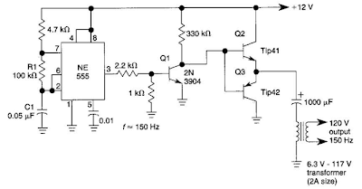
This dc-to-ac inverter is based on the popular 555. A 555 oscillator circuit drives a buffer amplifier consisting of Ql, Q2, and Q3.
The circuit operates at 150 to 160 Hz. Tl can be a 6.3-V or 12.6-V filament transformer as applicable.The frequency can be changed by changing the values of Rl and/or Cl.
Simple Dc/Ac Inverter Circuit Diagram
Tuesday, December 24, 2013
Current Monitor And Alarm
These circuits are intended for remote monitoring of the current consumption on the domestic mains line.

The circuit in Fig. I lights the signal lamp upon detecting a mains current consumption of more than 5 mA, and handles currents of several amperes with appropriate diodes fitted in the D, and D2 positions. Transistor Ti is switched on when the drop across D,-D2 exceeds a certain level. Diodes from the well-known I N400x series can be used for currents of up to I A, while lN540x types are rated for up to 3 A. Fuse F, should, of course, be dimensioned to suit the particular application.
A number of possible transistor types have been stated for use in the Ti position. Should you consider using a type not listed, be sure that it can cope with surges up to 700 V. As long as Ti does not con- duct, the gate of the triac is at mains potential via C,, protective resistor R2 and diode Da, which keeps C, charged. When Ti conducts, alternating current can flow through the capacitor, and the triac is triggered, so that Lai lights.

The circuit in Fig. 2 is a current triggered alarm. Rectifier bridge D4-D7 can only provide the coil voltage for Re, when the current through Di-D2 exceeds a certain level, because then series capacitor C, passes the alternating mains current. Capacitor C, may need to be dimensioned otherwise than shown to suit the sensitivity of the relay coil. This is readily effected by connecting capacitors in parallel until the coil voltage is high enough for the relay to operate reliably.
Finally, an important point: Many points in these circuits are at mains potential and therefore extremely dangerous to touch.
Source :http://www.ecircuitslab.com/2012/08/current-monitor-and-alarm-circuit.html
Monday, December 23, 2013
Simple RF Transmitter for PIR Sensors Circuit Diagram
This is the Simple RF Transmitter for PIR Sensors Circuit Diagram.

Sunday, December 22, 2013
Simple 2304 and 3456 MHz Power Amplifiers Circuit Diagram
This is a Simple 2304 and 3456 MHz Power Amplifiers Circuit Diagram

Subscribe to:
Posts (Atom)