Sunday, March 31, 2013
How to Make a Telephone Amplifier Circuit
The simple telephone ring tone amplifier circuit explained in this article saves the inconvenience of picking the telephone handset while speaking over a call. This circuit also particularly becomes useful when theres a need of the conversation to become audible to a number of people or a group of people.
When the conversation needs to become public the amplifier circuit simply needs to be switched ON so that rhe on going talks becomes amplified and can be heard loud and clear.
The most impressive feature of the proposed circuit design is that it does not require a direct or physical integration with the telephone line rather everything is done quite wirelessly.
The sensing of the telephone signals is done by the pick-up coil which may be placed very close to the telephone or the telephone wire.
The telephone pickup coil is made up of about 2000 to 3000 turns of 36 SWG super enameled copper wire wound over a plastic/paper former having a diameter of 2 inches.
Since this coil becomes the sole sensing agent should be made with lot of care and concentration.
Refer circuit diagram
When placed near to the telephone wire, the signals from the wire are transferred to the coil through the principle of mutual conduction and the audio pulses which is created by talking over the telephone mic is picked by the coil and sent to the main circuit for amplification.
The amplifier unit basically consists of the IC CA 3020 which forms the heart of the circuit. It just requires a few other passive components for the IC to become fully operational as en efficient audio amplifier.
The sensed input from the coil is not more than 300 mV, but becomes quite sufficient for the IC CA3020 to process the input into an amplified version over the connected loudspeaker.

Adjustments
After you finish assembling the circuit as shown in the figure, connect the pick up coil wire across the input of the amplifier and ground via the shown pot. Use shielded wire for this otherwise many unnecessary stray inputs may get into the amplifier. The pot acts as the sensitivity control or the volume control here.
Now switch on the power to the circuit.
Next gently place the pick up coil near the wire of the handset of the landline receiver.
Now as you lift the handset, the dial tone from the telephone should be heard loud and clear over the amplifier loudspeakers.
Make a call over the phone through another phone, all the audio during the calling procedure will be picked by the telephone amplifier circuit and converted into audible signals.
You may either use a battery for operating the circuit or a simple regulated power supply may be used. Alternatively you may use an AC DC adapter also for powering this circuit.
When the conversation needs to become public the amplifier circuit simply needs to be switched ON so that rhe on going talks becomes amplified and can be heard loud and clear.
The most impressive feature of the proposed circuit design is that it does not require a direct or physical integration with the telephone line rather everything is done quite wirelessly.
The sensing of the telephone signals is done by the pick-up coil which may be placed very close to the telephone or the telephone wire.
The telephone pickup coil is made up of about 2000 to 3000 turns of 36 SWG super enameled copper wire wound over a plastic/paper former having a diameter of 2 inches.
Since this coil becomes the sole sensing agent should be made with lot of care and concentration.
Refer circuit diagram
When placed near to the telephone wire, the signals from the wire are transferred to the coil through the principle of mutual conduction and the audio pulses which is created by talking over the telephone mic is picked by the coil and sent to the main circuit for amplification.
The amplifier unit basically consists of the IC CA 3020 which forms the heart of the circuit. It just requires a few other passive components for the IC to become fully operational as en efficient audio amplifier.
The sensed input from the coil is not more than 300 mV, but becomes quite sufficient for the IC CA3020 to process the input into an amplified version over the connected loudspeaker.
Adjustments
After you finish assembling the circuit as shown in the figure, connect the pick up coil wire across the input of the amplifier and ground via the shown pot. Use shielded wire for this otherwise many unnecessary stray inputs may get into the amplifier. The pot acts as the sensitivity control or the volume control here.
Now switch on the power to the circuit.
Next gently place the pick up coil near the wire of the handset of the landline receiver.
Now as you lift the handset, the dial tone from the telephone should be heard loud and clear over the amplifier loudspeakers.
Make a call over the phone through another phone, all the audio during the calling procedure will be picked by the telephone amplifier circuit and converted into audible signals.
You may either use a battery for operating the circuit or a simple regulated power supply may be used. Alternatively you may use an AC DC adapter also for powering this circuit.
Saturday, March 30, 2013
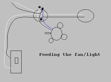
Hunter Ceiling Wiring Diagramsceiling Systems

English Espa Ol Fran Ais Portugu S Troubleshooting Guide.

Ceiling Fan Black And White Wire.

Wiring For A Ceiling Fan With Dual Switches Electrical Diy.

Jimmy Trucks And Suburban Enthusiasts Ceiling Fan Wiring Diagram.

Hot Wires And Neutral Wires Electrical Box.
Fan Body Thermostatic Ceiling Fan And Light Remote Control System.

Bracket Mounted Ceiling Fans Left Are Hung Directly From A.

Ceiling Electrical Fan Wiring By Gisella.

Hunter Ceiling Fan Wiring Diagrams Ceiling Systems.

Fans Ceiling Fans Ceiling Fan Accessories.
Friday, March 29, 2013
5 A Constant Voltage Constant Current Regulator Circuit
This is a design circuit for constant voltage constant current (CVCS) regulator doesn’t mean a system with a constant load, since there will be no regulation in such case. What we call CVCS regulator is a regulator with two modes. This is the figure of the circuit;

The first mode is constant voltage, where the regulator trying to regulate the supply to a variable load at a constant voltage. In this mode off course the current will be variable depending on the load. The current will vary a range that is limited to a predetermined maximum current level. When the load draw more current than this level then the regulator will switch to constant current mode, where the regulator keep the current at a fixed maximum value. Any attempt of the load to draw more current will cause the regulator to decrease the voltage as a reaction to keep it constant, so it acts like a current limiter. Here is the schematic diagram of the CVCS regulator.
R tC Servo Tester Circuit
Here’ s a design circuit for servo signal is a simple digital pulse. It spends most of its time at a logic low (0 V). About every 20mS it goes logic high (3 to 6 VDC) and then quickly goes low again. It is this tiny window of logic high time, called the pulse width, that gets the attention of the servo. Here’s the figure of the circuit;

Please refer to the drawing. The period labeled "A" is called the frame rate. In the example it is repeated every 20mS (50 times per second), which is quite typical for most radio systems.Modern servos define center as a 1.5mS pulse width, as shown by detail "B" in the drawing. Full servo rotation to one side would require that this pulse width be reduced to 1.0mS. Full rotation to the other side would require the pulse width to increase to 2.0mS. Any pulse width value between 1.0mS and 2.0mS creates a proportional servo wheel position within the two extremes. The frame rate does not need to change and is usually kept constant.
The servo will not move to its final destination with just one pulse. The servo amp designers had brilliantly considered that multiple pulses should be used to complete the journey. This little trick reduces servo motor current draw and it helps minimize erratic behavior when an occasional corrupt signal is received. To move the servo, you must repeat the pulse every few milliseconds, at the chosen frame rate. Modern R/C systems use a 40Hz - 60Hz frame rate, but the exact timing is not critical. If your frame rate is too slow, your servos movement will become rough. If the rate is too fast the servo may become very confused.
Thursday, March 28, 2013
Western Unimount Snow Plowwiringmountclassic
YBM)OGJDz+g~~_35.JPG)
Snow Plow Control Harness For Meyer E46 New Ebay.

Used 7 6 Western Unimount Snow Plow Wiring Mount 98 07 Classic Gmc.

Western Snow Plow Solenoid Snowplow Wiring Power Ebay.

Meyers Snow Plow Wiring Diagram.

Fisher Western Snow Plow Wiring Harness 26357 22413 2 Cable Ebay.

Snoway Snow Plow Light Set Eis 96107893 Arrow 780 Headlight Head Lamp.

Western Ultramount Flostat Hydraulic Unit Breakdown Plow Parts.

Touch Pad Control.

Western Plowsite Com Snow Plowing Ice Management Forum.

Kit Western Snow Plow Pump Kit 49211 7052 7049 Western Snow Plow.
Subscribe to:
Comments (Atom)